Click image to enlarge
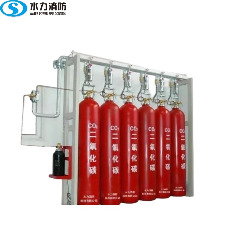
IG100 gas fire extinguishing system
Retail price
Market price
Weight
kg
Stock
隐藏域元素占位
Key words:
IG100 gas fire extinguishing equipment
- Product Description
-
- Commodity name: IG100 gas fire extinguishing system
1.System Overview
IG-100(NitrogenN2)It is a colorless, tasteless, non-conductive clean fire extinguishing gas, no residue after evaporation, and the density is similar to that of air. Its fire extinguishing mechanism is physical and can be used for total flooding fire extinguishing systems. The main components include storage containers, container valves, high-pressure hoses, check valves, headers, pressure relief devices, selector valves, nozzles and fire extinguishing agent delivery pipes.
2.system design and calculation
2.1 IG-100The design discharge time of the fire extinguishing agent shall not be greater60s.
2.2 IG-100The suppression time during fire fighting shall not be less10min.
2.3 IG-100Calculation of Design Dosage of System Extinguishing Agent
2.3.1 IG-100The design dosage of the system fire extinguishing agent shall be determined by calculation according to the design concentration of fire extinguishing or inerting corresponding to the combustibles in the protection area and the net volume of the protection area.
2.3.2 Protection zoneIG-100Design dosage of fire extinguishing or inerting can be calculated according to the following formula:

S=0.799678 0.00293*T
In the formula:W --Design dosage of total submergence fire extinguishing or design dosage of falling(kg);
K --Altitude correction coefficient of protection area
V --Net volume of protection zone(m3) ;
S--IG-100Extinguishing agent in101kPaSpecific volume of steam at atmospheric pressure and minimum ambient temperature in the guard zone(m3/kg);
T--Minimum ambient temperature in protection area(°C);
C --Fire extinguishing design concentration or inerting design concentration in protection area(%).
2.3.3 Used for savingA,B,C,EClass of fireIG-100The minimum design concentration of gas fire extinguishing system can be adopted according to the following table.:
IG-I00Minimum design concentration of fire extinguishing
Fire category
solid surface fire
Liquid and gas fire
Electronic products and communication equipment(Electrical)Fire
extinguishing concentration(Volume%)
30.0
33.6
31.9
Safety factor
1.2
1.3
1.2
Minimum design concentration of fire extinguishing(Volume%)
36.0
43.7
38.3
2.3.4 Maximum extinguishing concentration at the highest ambient temperature in the protection area:For the protection area where people often work should not exceedIG-100non-toxic reaction concentration( NOAEL)Concentration)43%;For the protection area where no one often works, or the protection area where people work at ordinary times but can ensure that all personnel can evacuate before the system is sprayed shall not exceedIG-100concentration of toxic reactions(LOAELConcentration)52%.
2.3.5 The inerting concentration shall be adopted for the protective area with explosion hazard, and the minimum inerting design concentration shall not be less than the inerting concentration of combustible substances in the protective area.1.1Times. The minimum inerting design concentration of some combustibles can be adopted according to the following table.:
IG-I00Inerting concentration and minimum inerting design concentration
Name of Combustible
inerting concentration(%)
Safety factor
Small inerting design concentration(%)
Methane
43.0
1.1
47.3
Propane
49.0
1.1
53.9
2.3.6 When there are many kinds of combustibles in the protection area, the design concentration of fire extinguishing or inerting shall be determined according to the largest one.
2.3.7 IG-100The storage amount of fire extinguishing agent of the fire extinguishing system shall be the sum of the design amount of fire extinguishing or inerting in the protection area and the remaining amount after spraying in the system. The remaining amount after the system is sprayed can generally be used according to the design amount.2%Estimate.
2.3.8 combined distribution systemIG-100The storage capacity of fire extinguishing agent shall be determined according to the protection area with the largest storage capacity.
2.3.9 Program and preliminary design phaseIG-I00The amount of extinguishing agent used in the system can be as per this drawingIG-100Gas Fire Extinguishing System Description TableIG-I00of the submergence coefficient multiplied by the net volume of the shelter area, dividedIG-I00The specific volume of steam is determined.
3.Area Calculation of Pressure Relief Port in Protection Area
The area of the pressure relief port in the protection zone can be calculated according to the following formula:

In the formula Fx--Pressure relief port area(m²) ;
Qx--IG-100Average discharge rate of extinguishing agent(kg/s) ;
Pt--Allowable pressure for the enclosure structure of the protection zone to withstand internal pressure(P a), given by the professional design of architecture and structure or see the general description of this atlas.7.3values in the table.
4 .Bottle storage room
The headroom of the bottle storage room should not be less2.4mits ground.(or floor)The carrying capacity can be2000kg/mconsider.
5 .System pipe network
5.1Nozzle
5.1.1 The protection area of a single nozzle should not be larger30m². The maximum installation height above the single-layer nozzle floor is5m. The protective area clearance height is greater5mAn additional layer of nozzles shall be added. Nozzles shall also be arranged when there are combustibles in the suspended ceiling of the protection area and in the raised floor. The minimum protective height of the nozzle is0.3m.
5.1.2 The arrangement of nozzles shall meet the requirements of uniform diffusion of fire extinguishing agent in the protective area after spraying. When the protection object is flammable liquid, the jet direction of the nozzle should not be aligned with the liquid surface.
5.1.3 Nozzles located in areas with dust shall be provided with a dust cover that can fall off on its own during spraying.
5.1.4 The nozzle should be installed close to the top surface of the protection area, and the maximum distance from the top surface should not be greater0.5m.
5.2Pipe network
5.2.1 For the material and interface mode of the pipe, please refer to the general description of this drawing.9.3related requirements.
5.2.2 The calculated value of the nozzle inlet pressure should not be less1.0MPa(absolute pressure).
5.2.3 Pipe diversion shall be three-way. The minimum flow of the three-way shunt shall not be less than the system flow5%.
5.2.4 Extinguishing agent pipeline shall not be laid in open air.
5.2.5 IG-100The fire extinguishing system is a single phase unsteady flow of gas. In order to ensure the uniform distribution of fire extinguishing agent and effective fire extinguishing, the system pipe network in the construction drawing stage must be accurately calculated. At the time of design, the calculation method or special computer software provided by the gas fire extinguishing system manufacturer or gas fire engineering company should be used to calculate the fire extinguishing agent delivery pipe network. The plan and preliminary design stage can be in accordance with this set of drawings.IG-100The pipe diameter is estimated in the "Pipe Diameter Estimation Table" in the description of the gas fire extinguishing system.
6 .System debugging
6.1 IG-100After the installation of the fire extinguishing system is completed, and the individual commissioning of the relevant automatic fire alarm system, automatic closing device at the opening of the protection area, ventilation machinery, fire damper and other linkage equipment is completed, the linkage commissioning of the fire extinguishing system shall be carried out.
6.2 Before commissioning, reliable safety measures shall be taken to ensure personnel safety and avoid accidental spraying of fire extinguishing agent.
6.3 The simulated jet test may be performed with compressed air or nitrogen. The structure, model and specification of the simulated gas storage container and the fire extinguishing agent storage container in the tested protection area shall be the same, the connection and control method shall be consistent, and the filling gas pressure and the fire extinguishing agent filling pressure shall be equal. The number of test containers shall not be less than the number of storage containers20%, and not less1A.
6.4 Automatic control shall be adopted for the simulated jet test.
6.5 The simulated jet test shall be:The test gas can be sprayed into the tested protection area, and it should be able to be sprayed from each nozzle in the tested protection area.;Relevant control valves shall work normally;The relevant sound and light alarm signals shall be accurate.;The equipment in the bottle storage room and the fire extinguishing agent delivery pipeline in the corresponding tested protection area shall be free of obvious shaking and mechanical damage.
1.System Overview
IG-100(NitrogenN2)It is a colorless, tasteless, non-conductive clean fire extinguishing gas, no residue after evaporation, and the density is similar to that of air. Its fire extinguishing mechanism is physical and can be used for total flooding fire extinguishing systems. The main components include storage containers, container valves, high-pressure hoses, check valves, headers, pressure relief devices, selector valves, nozzles and fire extinguishing agent delivery pipes.
2.system design and calculation
2.1 IG-100The design discharge time of the fire extinguishing agent shall not be greater60s.
2.2 IG-100The suppression time during fire fighting shall not be less10min.
2.3 IG-100Calculation of Design Dosage of System Extinguishing Agent
2.3.1 IG-100The design dosage of the system fire extinguishing agent shall be determined by calculation according to the design concentration of fire extinguishing or inerting corresponding to the combustibles in the protection area and the net volume of the protection area.
2.3.2 Protection zoneIG-100Design dosage of fire extinguishing or inerting can be calculated according to the following formula:

S=0.799678 0.00293*T
In the formula:W --Design dosage of total submergence fire extinguishing or design dosage of falling(kg);
K --Altitude correction coefficient of protection area
V --Net volume of protection zone(m3) ;
S--IG-100Extinguishing agent in101kPaSpecific volume of steam at atmospheric pressure and minimum ambient temperature in the guard zone(m3/kg);
T--Minimum ambient temperature in protection area(°C);
C --Fire extinguishing design concentration or inerting design concentration in protection area(%).
2.3.3 Used for savingA,B,C,EClass of fireIG-100The minimum design concentration of gas fire extinguishing system can be adopted according to the following table.:
IG-I00Minimum design concentration of fire extinguishing
|
Fire category |
solid surface fire |
Liquid and gas fire |
Electronic products and communication equipment(Electrical)Fire |
|
extinguishing concentration(Volume%) |
30.0 |
33.6 |
31.9 |
|
Safety factor |
1.2 |
1.3 |
1.2 |
|
Minimum design concentration of fire extinguishing(Volume%) |
36.0
|
43.7
|
38.3 |
2.3.4 Maximum extinguishing concentration at the highest ambient temperature in the protection area:For the protection area where people often work should not exceedIG-100non-toxic reaction concentration( NOAEL)Concentration)43%;For the protection area where no one often works, or the protection area where people work at ordinary times but can ensure that all personnel can evacuate before the system is sprayed shall not exceedIG-100concentration of toxic reactions(LOAELConcentration)52%.
2.3.5 The inerting concentration shall be adopted for the protective area with explosion hazard, and the minimum inerting design concentration shall not be less than the inerting concentration of combustible substances in the protective area.1.1Times. The minimum inerting design concentration of some combustibles can be adopted according to the following table.:
|
IG-I00Inerting concentration and minimum inerting design concentration |
|||
|
Name of Combustible |
inerting concentration(%) |
Safety factor |
Small inerting design concentration(%) |
|
Methane |
43.0 |
1.1 |
47.3 |
|
Propane |
49.0 |
1.1 |
53.9 |
2.3.6 When there are many kinds of combustibles in the protection area, the design concentration of fire extinguishing or inerting shall be determined according to the largest one.
2.3.7 IG-100The storage amount of fire extinguishing agent of the fire extinguishing system shall be the sum of the design amount of fire extinguishing or inerting in the protection area and the remaining amount after spraying in the system. The remaining amount after the system is sprayed can generally be used according to the design amount.2%Estimate.
2.3.8 combined distribution systemIG-100The storage capacity of fire extinguishing agent shall be determined according to the protection area with the largest storage capacity.
2.3.9 Program and preliminary design phaseIG-I00The amount of extinguishing agent used in the system can be as per this drawingIG-100Gas Fire Extinguishing System Description TableIG-I00of the submergence coefficient multiplied by the net volume of the shelter area, dividedIG-I00The specific volume of steam is determined.
3.Area Calculation of Pressure Relief Port in Protection Area
The area of the pressure relief port in the protection zone can be calculated according to the following formula:
In the formula Fx--Pressure relief port area(m²) ;
Qx--IG-100Average discharge rate of extinguishing agent(kg/s) ;
Pt--Allowable pressure for the enclosure structure of the protection zone to withstand internal pressure(P a), given by the professional design of architecture and structure or see the general description of this atlas.7.3values in the table.
4 .Bottle storage room
The headroom of the bottle storage room should not be less2.4mits ground.(or floor)The carrying capacity can be2000kg/mconsider.
5 .System pipe network
5.1Nozzle
5.1.1 The protection area of a single nozzle should not be larger30m². The maximum installation height above the single-layer nozzle floor is5m. The protective area clearance height is greater5mAn additional layer of nozzles shall be added. Nozzles shall also be arranged when there are combustibles in the suspended ceiling of the protection area and in the raised floor. The minimum protective height of the nozzle is0.3m.
5.1.2 The arrangement of nozzles shall meet the requirements of uniform diffusion of fire extinguishing agent in the protective area after spraying. When the protection object is flammable liquid, the jet direction of the nozzle should not be aligned with the liquid surface.
5.1.3 Nozzles located in areas with dust shall be provided with a dust cover that can fall off on its own during spraying.
5.1.4 The nozzle should be installed close to the top surface of the protection area, and the maximum distance from the top surface should not be greater0.5m.
5.2Pipe network
5.2.1 For the material and interface mode of the pipe, please refer to the general description of this drawing.9.3related requirements.
5.2.2 The calculated value of the nozzle inlet pressure should not be less1.0MPa(absolute pressure).
5.2.3 Pipe diversion shall be three-way. The minimum flow of the three-way shunt shall not be less than the system flow5%.
5.2.4 Extinguishing agent pipeline shall not be laid in open air.
5.2.5 IG-100The fire extinguishing system is a single phase unsteady flow of gas. In order to ensure the uniform distribution of fire extinguishing agent and effective fire extinguishing, the system pipe network in the construction drawing stage must be accurately calculated. At the time of design, the calculation method or special computer software provided by the gas fire extinguishing system manufacturer or gas fire engineering company should be used to calculate the fire extinguishing agent delivery pipe network. The plan and preliminary design stage can be in accordance with this set of drawings.IG-100The pipe diameter is estimated in the "Pipe Diameter Estimation Table" in the description of the gas fire extinguishing system.
6 .System debugging
6.1 IG-100After the installation of the fire extinguishing system is completed, and the individual commissioning of the relevant automatic fire alarm system, automatic closing device at the opening of the protection area, ventilation machinery, fire damper and other linkage equipment is completed, the linkage commissioning of the fire extinguishing system shall be carried out.
6.2 Before commissioning, reliable safety measures shall be taken to ensure personnel safety and avoid accidental spraying of fire extinguishing agent.
6.3 The simulated jet test may be performed with compressed air or nitrogen. The structure, model and specification of the simulated gas storage container and the fire extinguishing agent storage container in the tested protection area shall be the same, the connection and control method shall be consistent, and the filling gas pressure and the fire extinguishing agent filling pressure shall be equal. The number of test containers shall not be less than the number of storage containers20%, and not less1A.
6.4 Automatic control shall be adopted for the simulated jet test.
6.5 The simulated jet test shall be:The test gas can be sprayed into the tested protection area, and it should be able to be sprayed from each nozzle in the tested protection area.;Relevant control valves shall work normally;The relevant sound and light alarm signals shall be accurate.;The equipment in the bottle storage room and the fire extinguishing agent delivery pipeline in the corresponding tested protection area shall be free of obvious shaking and mechanical damage.

Online Message
Product classification

Official website

Official account
Page Copyright © Water Power Fire Control Co.,Ltd
Address: No.57, Ximei Guifeng Industrial Zone, Quanzhou, Fujian, China


